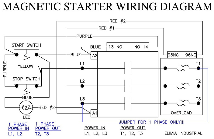
Below is a generic wiring diagram for an IEC motor starter.
With this design the voltage to power the contactor is "taken" from two legs of the supply power, L1 and L2. This means that this set up will have a coil voltage same as supply Voltage. This diagram can be used for 230V 3 phase, 230V 1 phase and 480V 3 phase. Elimia calls this a DOL type. Can also be called a three wire latching starter.
How it works. Starting from L2 which will be one leg of your power supply. Red #1 runs to connection 95 on the overload. 95 and 96 are the normally closed contact of the overload. If your starter trips this N/C contact will open causing the starter to disengage. From 96 Red #2 travels to coil connection A1. If A1 does not have power the contactor will not engage.
From L1 which is the second leg of your power supply, Yellow, we feed a constant hot leg to the push button switch stop button. Stop buttons are almost always N/C. So under normal conditions power passes through the stop switch to the Purple wire. Then it jumps to the start button. So at this point power is on one side of the start button and waiting.... Once the start button is pressed, power passes through and comes out on the Blue wire and finally making it to the coil connection A2.
So, with the start button pressed you have power at A2 and from above you have another leg of power on A1. Whoala, the starter engages! But, without the "latch" circuit the starter would disengage as so as the start button is released. That is where the Purple wire feeding contact 14 comes in to play. The same power phase that feeds the start button feeds contact 14 and then exits on 13. When the contactor engages the N/O contact set becomes closed. So when start button is pushed and powers A2, at the same time jumper wire Blue between A2 and 13 gets power. When the start button is released there is a patch created through 13 and 14 to continue to supply power to A2 thus latching the starter engaged. This latch is broken by pressing the stop button or losing main power.
Additionally in this wiring diagram there is an indicator light. This light is wired to show when the starter is engaged. Just like A2 which is backfed through 13 and 14, the power travels up the Blue wire eventually making it to one side of the light. The other side of the light is perminently connected to A1 completing the circuit, unless tripped by 95 and 96.
On more thing, on this generic diagram there are special connections and a jumper shown in blue. In order to use a 3 phase starter on single phase 230V a jumper must be installed. Since the overload is "looking" for power passing through all 3 load connections T1, T2 and T3 the jumper must be installed for accurate trips. So note the line side connections in this configuration, power is applied to L1 and L2. Now note the load side connections, T2 and T3. The jumper shown in blue is basically just running one leg of the single phase through the starter two times!